Stay awhile and listen… The ESP8266 series has long been a favorite for IoT enthusiasts due to its affordability and versatility. Among the various iterations of the ESP8266, the ESP-01 and its sibling, the ESP-01S, have garnered attention for their compact size and built-in WiFi capabilities. However, as time goes by, newer and more advanced microcontrollers have emerged, rendering these older models somewhat obsolete for newer projects. Nevertheless, if you find yourself with a bunch of ESP-01/ESP-01S modules gathering dust in an old box (like I did), have no fear! In this post, I’ll show how to construct a custom development board custom-made specifically for them.
Differences between ESP-01 and ESP-01S
Before continuing, let’s briefly see the distinctions between the ESP-01 and the ESP-01S. While both modules are based on the ESP8266 chip and share many similarities, the ESP-01S has a bigger flash memory (usually a 4 MByte flash) and no power LED or TX LED, compared to its predecessor, the ESP-01. There are other minor changes like pullup resistors and fewer components on board however, in terms of pinout and functionality, they are largely identical, making them interchangeable for most projects.
As the ESP-01S usually has a flash memory 4 times bigger than the ESP-01 model, it can be upgraded with newer and bigger firmware.
Breadboard foe
Due to their age and limitations, the ESP-01/ESP-01S modules are not the most suitable choice for your newer hobby projects. Even back then, when these modules were the new guys on the block, they were not well-liked by hobbyists because they were not breadboard-friendly due to their connectors.
By constructing a dedicated development board, we can facilitate the prototyping with a breadboard and make experimentation.
Building the Development Board
Be warned that you could damage the USB port of your computer and cause harm to yourself and the people around you by messing around with the soldering iron. Read the disclaimer here.
The main goals for this development board are:
- Facilitate use with a breadboard
- Provide a 3.3V power line for the ESP module
- Grant easy access to all necessary pins
- Simplifies the programming process
- Provide voltage level shifting from 5V to 3.3V for the module RX serial line
Requirements
- Compatibility with ESP-01/ESP-01S Modules: The development board must be compatible with both the ESP-01 and ESP-01S modules, accommodating their pinout and form factor.
- Easy Access to GPIO Pins: One of the primary goals of the development board is to provide convenient access to GPIO pins for interfacing with sensors, actuators, and other peripherals. Therefore, it should include male headers that expose all GPIO pins of the ESP-01/ESP-01S modules.
- Programming Interface: As the ESP-01/ESP-01S modules lack an onboard USB interface for programming, the development board should incorporate a mechanism for programming and debugging. This will involve a serial-to-USB adapter.
- Programming Mode: Incorporate a jumper or switch for easy boot into programming mode.
- Power Regulation: To ensure stable operation of the ESP-01/ESP-01S modules, the development board should integrate a voltage regulator capable of providing a reliable 3.3V power supply.
- Reset Functionality: Incorporating a reset button or switch is essential for resetting the ESP-01/ESP-01S modules, facilitating easy reprogramming and troubleshooting.
- Indicator LEDs: Including indicator LED for power, providing visual confirmation of power supply.
- Compact Design: While accommodating all necessary components and features, the development board should maintain a compact form factor.
- Ease of Assembly: The construction of the development board should be straightforward, utilizing commonly available components and simple soldering techniques.
Design
I usually prefer a more structured approach to designing my perfboard layout. I like to do the schematics and board layout with KiCad, a popular open-source EDA (Electronic Design Automation) software.
Schematics
First, we have to build the schematics with all the components. I like to slice the schematics into small circuits using labels to connect them like the one below.
I chose to use the LM317 as a voltage regulator because I have plenty of them but you could use any 3.3V regulator for this project. Remember that the ESP-01 module requires at least 100mA but can spike more than 300mA.

Some more small circuits like the reset button, power LED, connectors, etc.

Place and Route
After finishing the schematics and assigning the component’s footprint, we have to choose a perfboard model, place the components and do the wiring.
For this design, I chose a small perfboard that I had in my collection. A generic double-side perfoboard with 2 x 8cm, easily found at Amazon, Aliexpress or eBay.

The first step to layout your custom board is to configure the grid with 2.54mm (for thru-hole components) and draw the boundaries of your real perfboard. You can also use the measuring tool to draw the size as a guide like I did.

Take your time to place the components and remember that you’ll have to do the wire soldering by hand, so think twice before placing a component. The more time you spend here the less time you spend wiring and soldering.

Yet using KiCad, I draw vertical and horizontal lines over the components and mark each vertical line with an alphabet letter and each horizontal line with a number at the “User Draw” layer to build a “map” for soldering. Now you just have to print this map (scaled up) and use it as a guide for placing components.
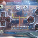
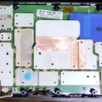
Assembly Complete
By far, soldering the components is the most time-consuming and annoying job because we have to strip wires at a specific length and the soldering iron must be at a specific temperature so we can bridge holes. If the soldering iron is too hot, you’ll melt the solder blob and you’ll not be able to bridge holes, if it is too cold, the solder will not even melt.

The pin headers at the middle of the board should be voltage dividers to be used when necessary but I soldered only the headers and left the resistors holes for another time.

All the wires were cut with a scalpel and fine tweezers.

At soldering time I replaced one of the LM317 resistors with a multi-turn potentiometer. This improves fine voltage control.

The development board was meant to be used with a USB to serial adapter connected to it. There is a voltage divider between the RX pin of the module and the TX pin of the USB to serial adapter providing a safe voltage level for the module.
Testing
Before powering the board or even connecting it to the de USB port, double-check the power lines and the RX module voltage divider!
Now comes the moment of truth! Connecting the ESP module to the development board and the development board to the USB port with the USB to serial adapter, you should have the power LED on.
I am using Linux and command line tools to test the board. If you are using Windows, I’m sorry, you can use the ESPlorer tool to test your board.
Now using the esptool type this command to read the chip ID:
esptool -p /dev/ttyUSB0 -b 115200 -c esp8266 chip_idYou should get some output like this:
esptool.py v2.8
Serial port /dev/ttyUSB0
Connecting….
Chip is ESP8266EX
Features: WiFi
Crystal is 26MHz
MAC: xx:xx:xx:xx:xx:xx
Enabling default SPI flash mode…
Chip ID: 0x00c227e2
Hard resetting via RTS pin…
Again using the esptool type this command to read the flash memory ID:
esptool -p /dev/ttyUSB0 -b 115200 -c esp8266 flash_idYou should get some output like this:
esptool.py v2.8
Serial port /dev/ttyUSB0
Connecting…
Chip is ESP8266EX
Features: WiFi
Crystal is 26MHz
MAC: xx:xx:xx:xx:xx:xx
Enabling default SPI flash mode…
Manufacturer: 5e
Device: 6014
Detected flash size: 1MB
Hard resetting via RTS pin…
Conclusion
While ESP-01/ESP-01S modules may not be the go-to choice for contemporary IoT projects, by providing easy access to GPIO pins, simplifying the programming process, and incorporating additional features like power regulation and reset functionality, our DIY board transforms these outdated modules into viable tools for prototyping and experimentation. So, if you find yourself rummaging through an old box of electronics and stumble upon a collection of ESP-01/ESP-01S modules, don’t discard them just yet! Instead, embrace the opportunity to breathe new life into these forgotten components.
See ya!