Hey listen…, electronic devices have become an integral part of our lives, providing or enhancing education, safety, medical care and entertainment on the go. However, like any device, it can break or develop faults over time. Although the new trend dictates throwing broken electronics in the trash, I will walk you through the process I used to diagnose a faulty multi-source audio player and what I did to fix it.
Identify the Problem
The first step in diagnosing and repairing any faulty electronic device is to understand and identify the problem. There are thousands of ways something can fail, for example, if your device has no power. That is, the device doesn’t turn on at all, there is no light, no sound no movement no nothing that indicates that it’s operating. It could be due to a dead battery or faulty charger, a faulty power button, or a problem with the internal circuitry.
I could write an entire post just to list some of the odd ways a device can fail but in this post, I will focus on a particular device with a particular problem. You should always think simply and if you cannot find the problem, you should think about more complicated things.
The Device
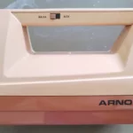
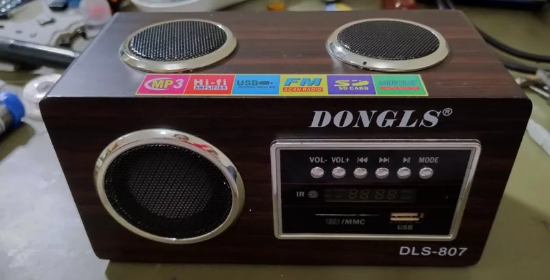
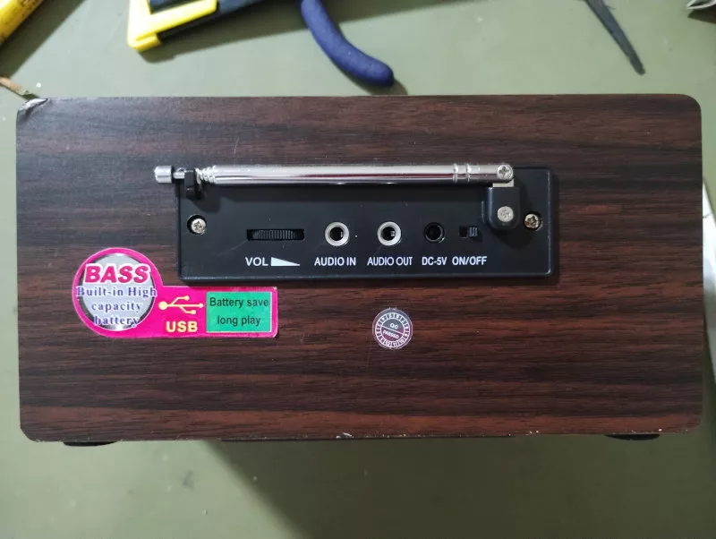
The device I worked on was a small and cheapy, battery-powered FM radio/audio player that could read audio files, a.k.a. mp3, from SDCards and USB flash drives and also had an auxiliary input jack, which is neat!
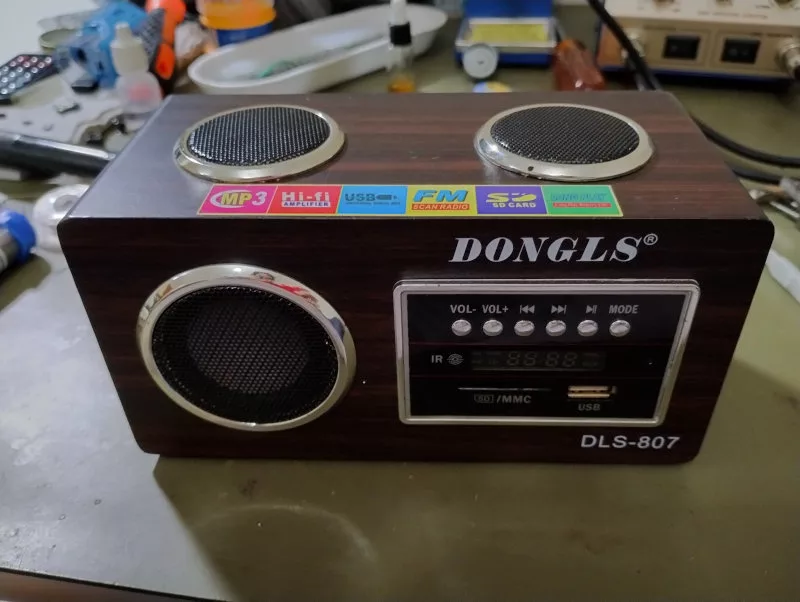
I don’t know why but many cheap Chinese products have to have something odd or fake in them. This one had a fake speaker. One of the top speakers was fake and it was hard to tell which one was the fake one. I know now because I opened the device and saw it guts!
![Top speakers. One is fake =]](https://raffsalvetti.dev/wp-content/uploads/2023/10/IMG_20231001_205534468_-jpg.webp)
Tools and Materials
Before you start diagnosing and repairing electronics, make sure you have the following tools and materials:
- A clean workspace with good lighting
- Screwdrivers (usually Phillips and sometimes Torx)
- Multimeter (could be cheap as a flock but it must be a reliable one)
- Soldering iron (I like the temperature-controllable ones but could be the simplest depending on the type of electronics)
- Solder, of course (flux is good to have)
- Oscilloscope (someday you’ll need a simple one)
- Small plastic prying tools (I use cheap guitar picks)
Diagnose the problem
The problem with my little patient was that one of the two speakers (the real ones =]) suddenly stopped to play sounds. This scenario was always present, no matter if the audio source was FM radio, USB flash driver or the SDCard. Also, I tried to mess around with the buttons or the volume pot and the problem was still there.
Now is a good time to ask you to read the disclaimer page =].
Disassembly
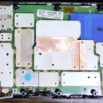
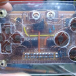
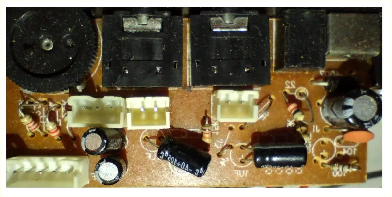
I removed the back panel (that one with audio input and output jack) and discovered that there were two boards, one for the radio tuning, card reader, read buttons, drive the display, and all that jazz and another board with the audio amp. My attention was focused on the second board because I started to track the issue from de output (the speakers) to the input (probably a microcontroller).
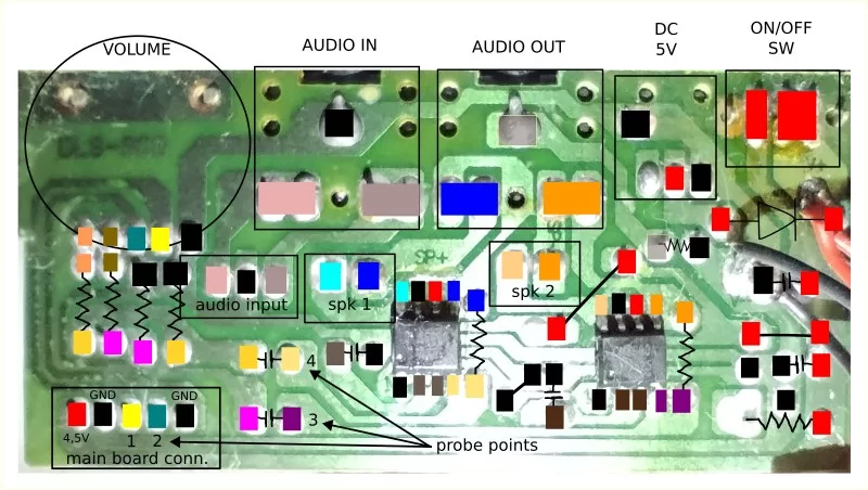
Multimeter Probing
First of all, I used the multimeter to measure the speakers not connected to the board. Both were good, with 4 ohms each. Then I measured spk 1 and spk 2, which are the speaker connectors, in reference to ground and I got around 2v on both! That was a surprise. I was expecting one of them to be shorted to ground. Before checking the voltages at spk 1 and spk 2 I was guessing that one of the chips went faulty, and I expected most of its pins with no voltage but that was not the case.
As the first observations were not conclusive, I searched for the integrated circuit datasheet. The chip marking was CM8600A, a 3-watt audio amplifier with a shutdown pin.
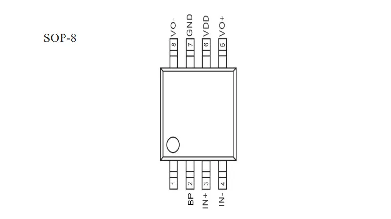
For this particular circuit, a datasheet is not really required because we can assume, with a basic understanding of audio amplifiers, that the chip must have at least one pin for input and another pin for output. In this way, one could follow the trace from the speaker connector to the chip, maybe expecting some passive component in between, and find the output pin.
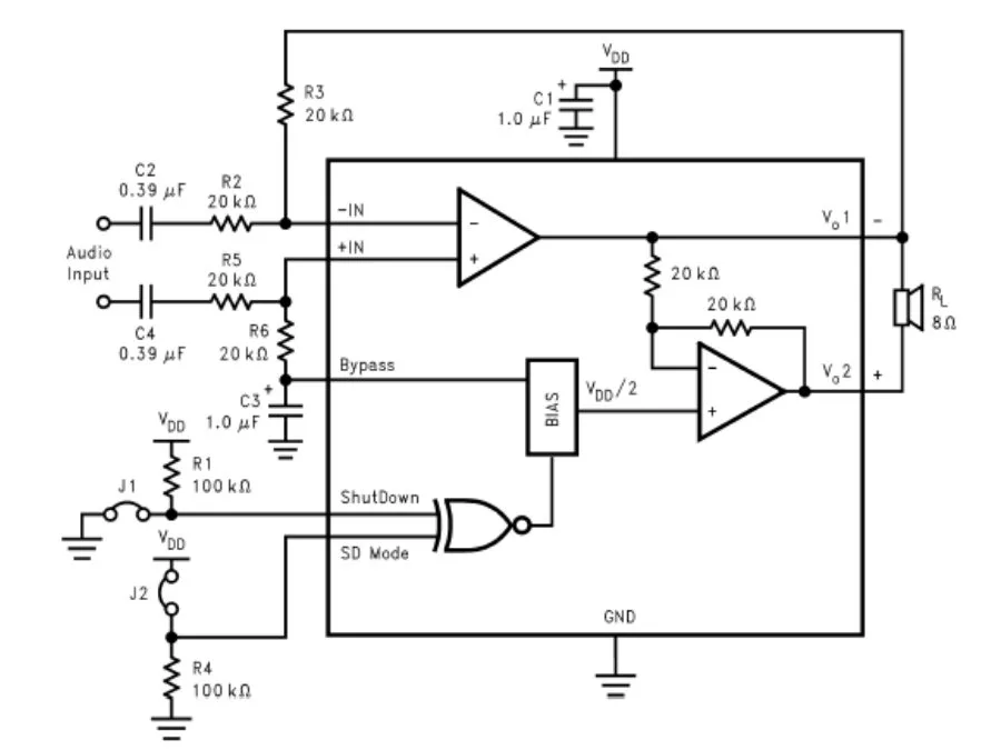
The pinout figure and this example circuit, both extracted from the datasheet, show what we’ve got at the board.
After some more time probing around with the multimeter, I noticed that pin 4 of one of the chips was practically stable at 2v while the same pin on the other chip was oscillating a bit. Besides that, both chips seemed to be good.
Oscilloscope Probing
At this point, I was just guessing the faulty IC again, based on a little difference between the reading on pin 4. So, I decided to use the oscilloscope and probe the input and output pins. As expected, I got some messy waveforms because I was playing some random music.
To get a better idea of the waveforms, I used ffmpeg to create a stereo mp3 file with a particular tone frequency on each channel. For the left channel, I chose 550Hz and for the right channel 440Hz.
ffmpeg -f lavfi -i "sine=frequency=550:sample_rate=48000:duration=300" -f lavfi -i "sine=frequency=440:sample_rate=48000:duration=300" -filter_complex "[0:a]aformat=sample_fmts=fltp:sample_rates=44100:channel_layouts=mono,volume=4[a1];[1:a]aformat=sample_fmts=fltp:sample_rates=44100:channel_layouts=mono,volume=4[a2];[a1][a2]amerge" -y L550hz_R440hz.mp3I’m using Linux and I can use ffmpeg it from a simple terminal emulator. If you are using Windows (without the Linux subsystem), I’m really sorry for you.
I loaded the generated mp3 file on an SDCard, just because I could, and started to probe again. This time I got a clear view of the problem. One of the chips, the one with the quiet pin 4, was dead. The input signal was good but there was no output. Moreover, I was able to find out that the volume control was not working properly!
Here are some pictures of the waveforms. I do not have the waveform of the dead chip because it was a flat line around the 2v.
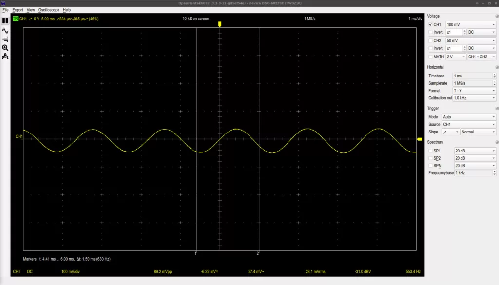
This is the waveform of the left channel, probing the pin marked as “probe point 2” at the bottom left of the audio amp board.

This is the waveform of the right channel, probing the pin marked as “probe point 1” at the bottom left of the audio amp board.

This is the waveform of the right channel, probing the pin marked as “probe point 3” after the input capacitor. There was a little noise but I couldn’t hear it from the speaker.
Solution
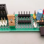
The simplest solution to this kind of problem is to replace the faulty component. Unfortunately, the local electronic component supplier did not have this chip or a possible replacement. Also, I would need two of these chips because this device had a twin brother with the same problem. So I decided to transplant the functional chip to the brother and for this guy, I chose a more invasive procedure. I built an extension board with another audio amplifier.
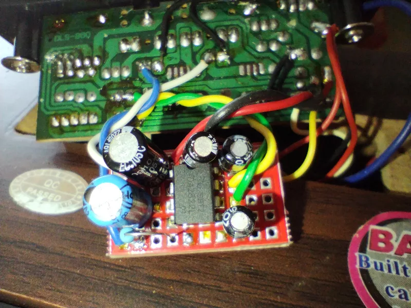
I used a DIP dual power amp, the TDA2822M that I had in my parts stash. It’s a good choice for this kind of project because is a low-supply voltage chip, it can operate at voltages down to 1.8v, ideal for battery-powered devices like this one.
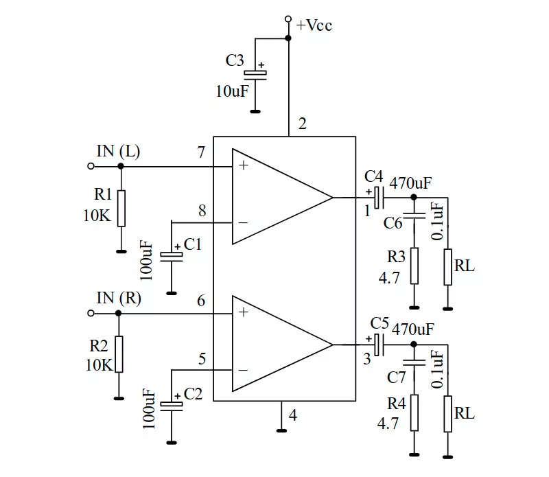
I used this example circuit provided by the TDA2822M datasheet for the extension board. Of course, I changed some passive components like the output capacitors and input resistors to fit my needs (all empirically =]). Also, I had to remove a pair of resistors (output) and change a pair of capacitors (input) from the original board.

That was a pretty small perfboard to work on. The soldering was made with a pair of tweezers and a fine soldering iron tip. Fortunately, all went well and the amp was working nicely.
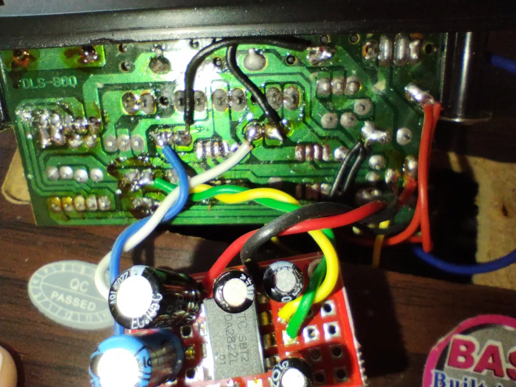
Is worth mentioning that the wiring should be as small as it could be to avoid interference, particularly at the input lines.
I built the same circuit on a small breadboard using long wires for the power supply, inputs and outputs. The breadboarded circuit tricked me for a while because it was extremely noisy with a lot of hum, I even thought the chip was defective. A decoupling capacitor is mandatory here!
Conclusion
Diagnosing and repairing any faulty electronics can be rewarding. Not only by resurrecting a piece of dead equipment and reducing e-waste but also because we can learn a bunch of new stuff. By identifying the problem, gathering the necessary tools, and finding suitable replacement parts or adapting them as needed, you can bring devices back to life.
Warning note here: Always exercise caution and prioritize safety, especially when working with electronics. If you don’t have the necessary skills yet, go to a repair shop to ensure a successful repair.