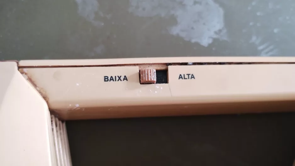
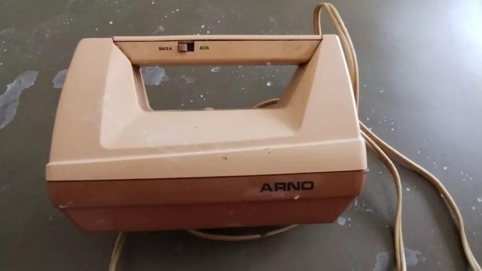
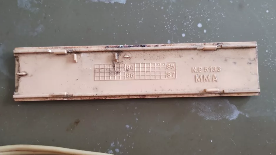
If you grew up in Brazil between the 80s and 90s, chances are you’ve seen an Arno hand mixer (model MMA) in action, whipping cream for weekend desserts, mixing cake batter for birthdays, or helping prepare the family’s weekend recipes. These mixers were sturdy, practical, and built to last, which makes them perfect candidates for restoration today.
In this post, I’ll share the process of restoring one of these devices, from the moment I found it lifeless to the satisfying first test after bringing it back to life.
A Brief History of the Brand Arno
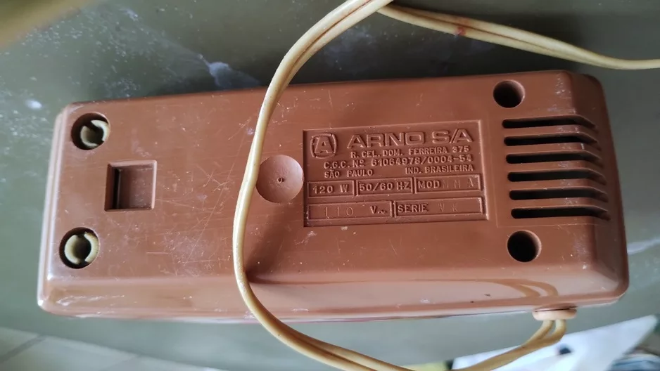
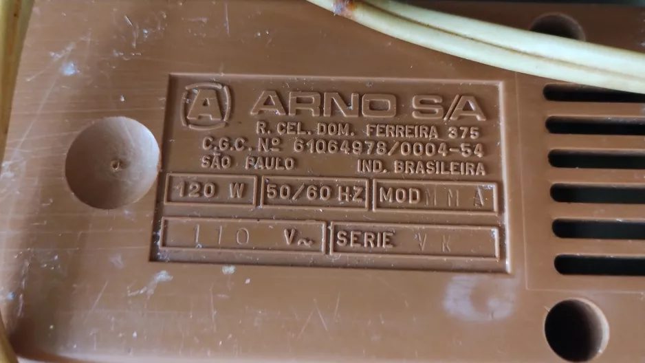
Arno is a Brazilian company specializing in household appliances, particularly small electric appliances. Founded in 1938 under the name Construções Eletromecânicas Brasileiras Ltda., it initially focused on producing and selling electric motors. Over the decades, the company expanded its product line, entered the household appliance market, and established itself nationwide. In 1944, it merged with other companies to form Empresas Reunidas e Comércio Arno S.A., officially adopting the name Arno in 1945. By the late 1940s, it was selling products across Brazil, and in the 1960s, it began exporting blenders to Europe and Latin America. The company also diversified into the automotive sector in the 1970s and became the first in Brazil to produce electric drills after acquiring Skil in 1975. You can read more at Wikipedia (in Brazilian Portuguese).
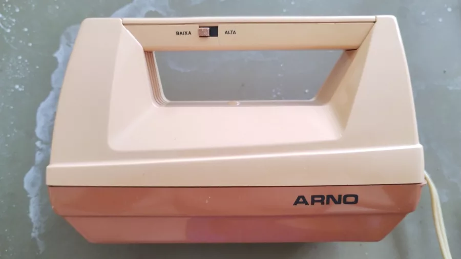
Initial Condition
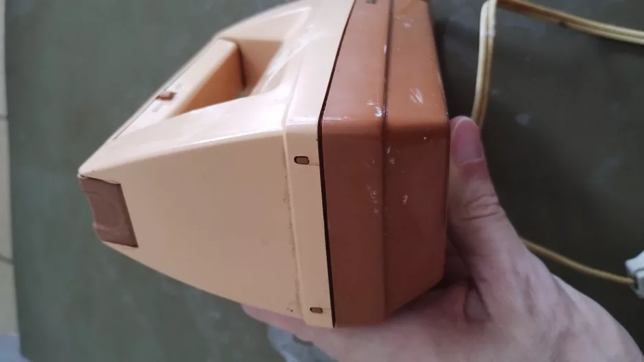
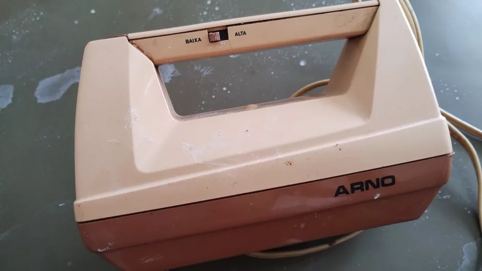
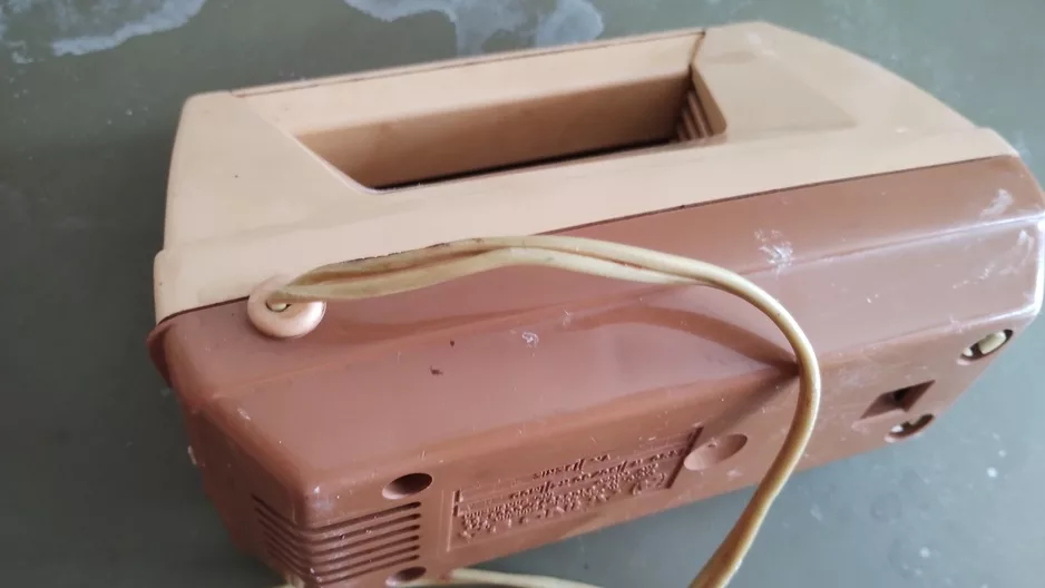
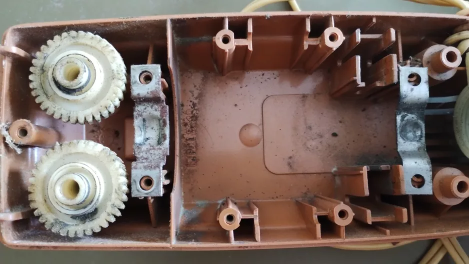
When I first picked up the mixer, it was… well, tired.
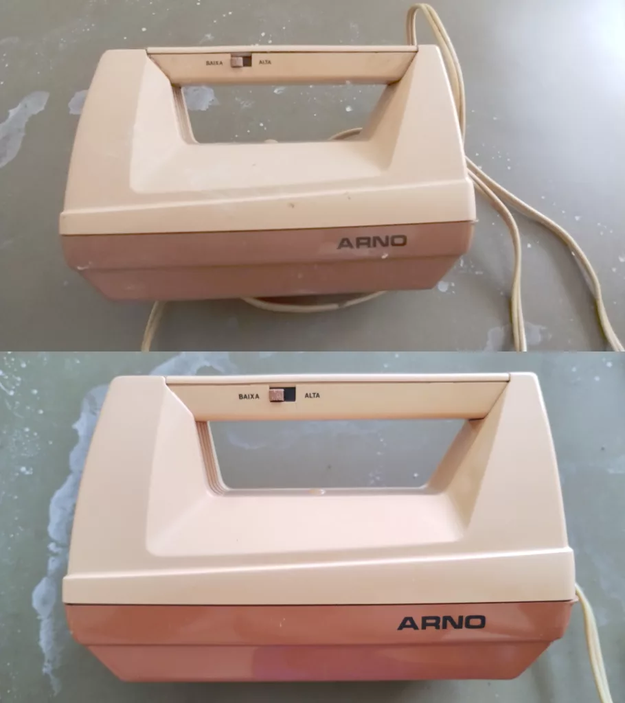
The exterior shell was not particularly dirty, with some kitchen grime and scratches; however, the motor was not functioning at all, and the gears were stuck. The power cord insulation was also dirty, and the original beaters were intact but dirty.
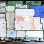
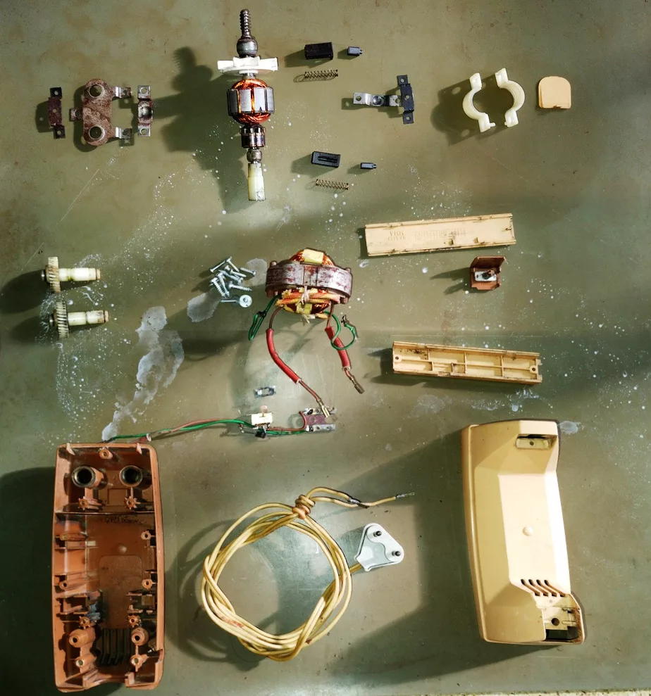
Disassembly
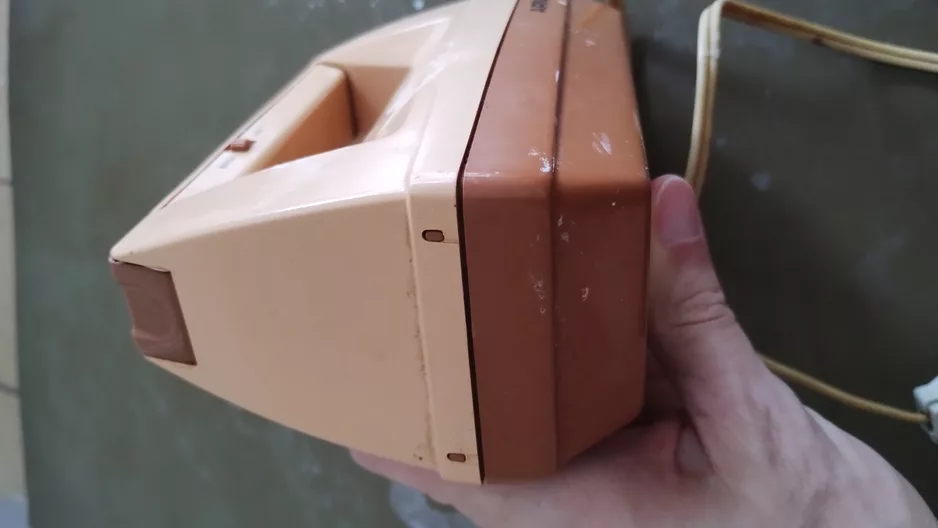
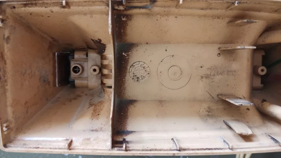
The MMA’s design made this step straightforward. Instead of plastic clips, only two strudy scews were holding the external assembly.
Cleaning and Restoration
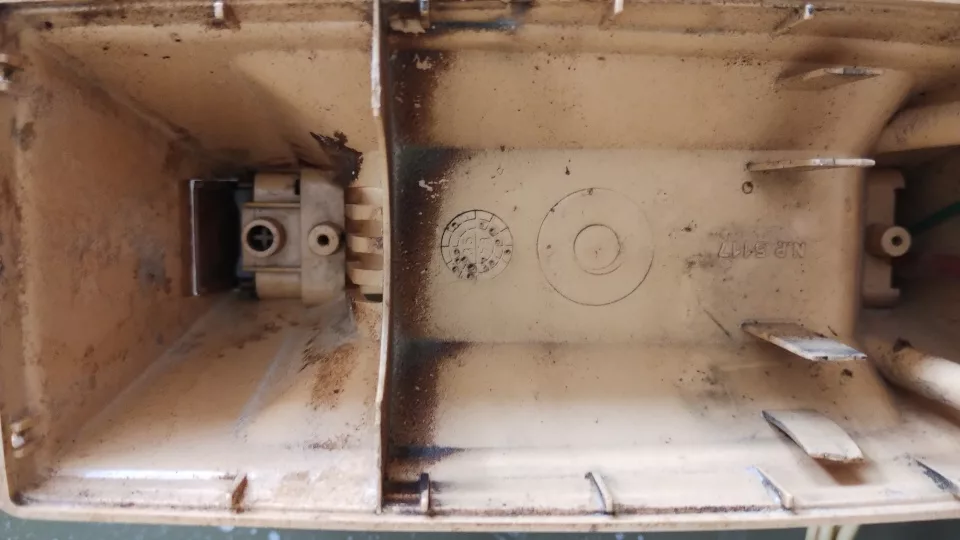
Plastic housing
I soaked the outer shell in warm water with dish detergent, then scrubbed gently with a soft plastic brush. For more dirty areas, I used a soaked rag with querosene and then rinsed with water and dish detergent.
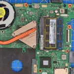
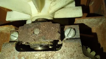
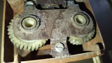
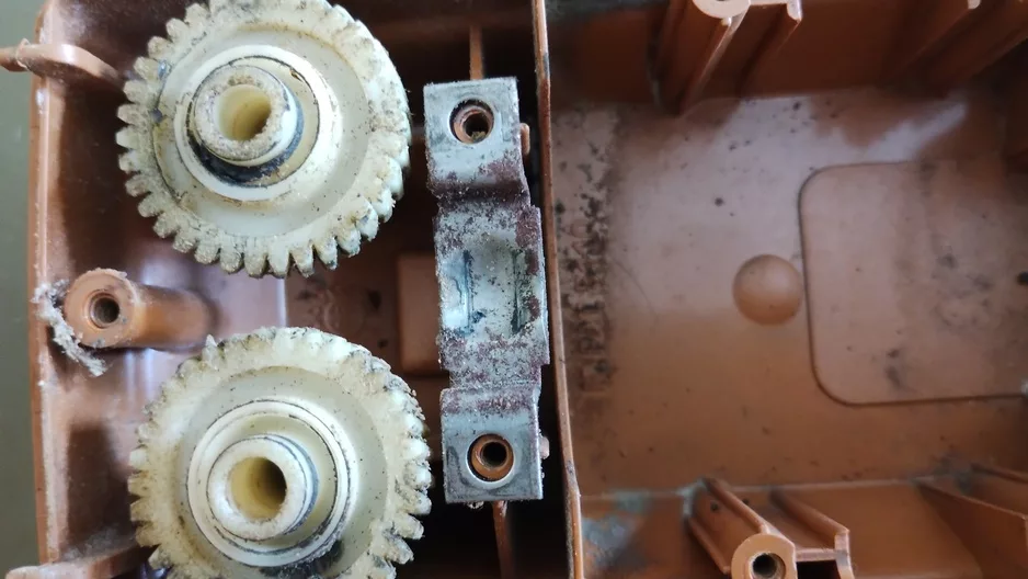
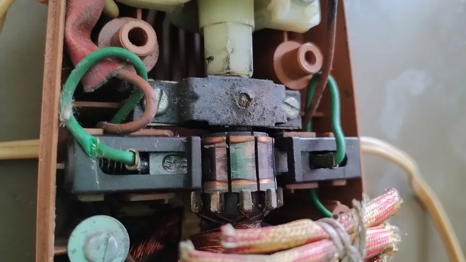
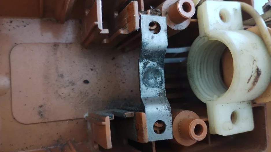
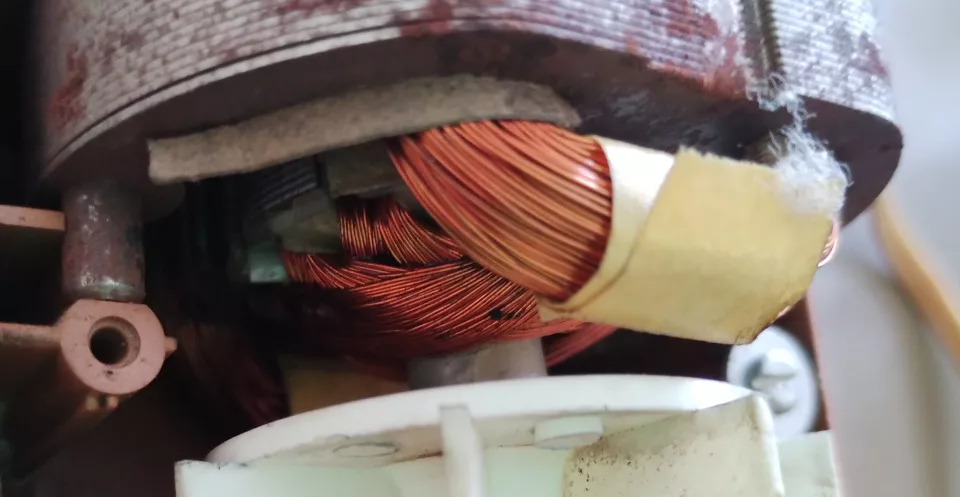
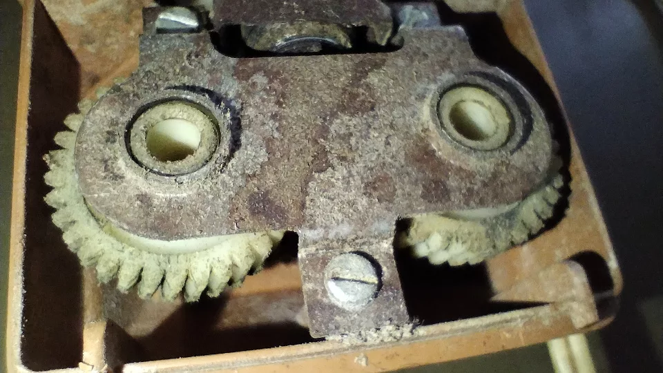
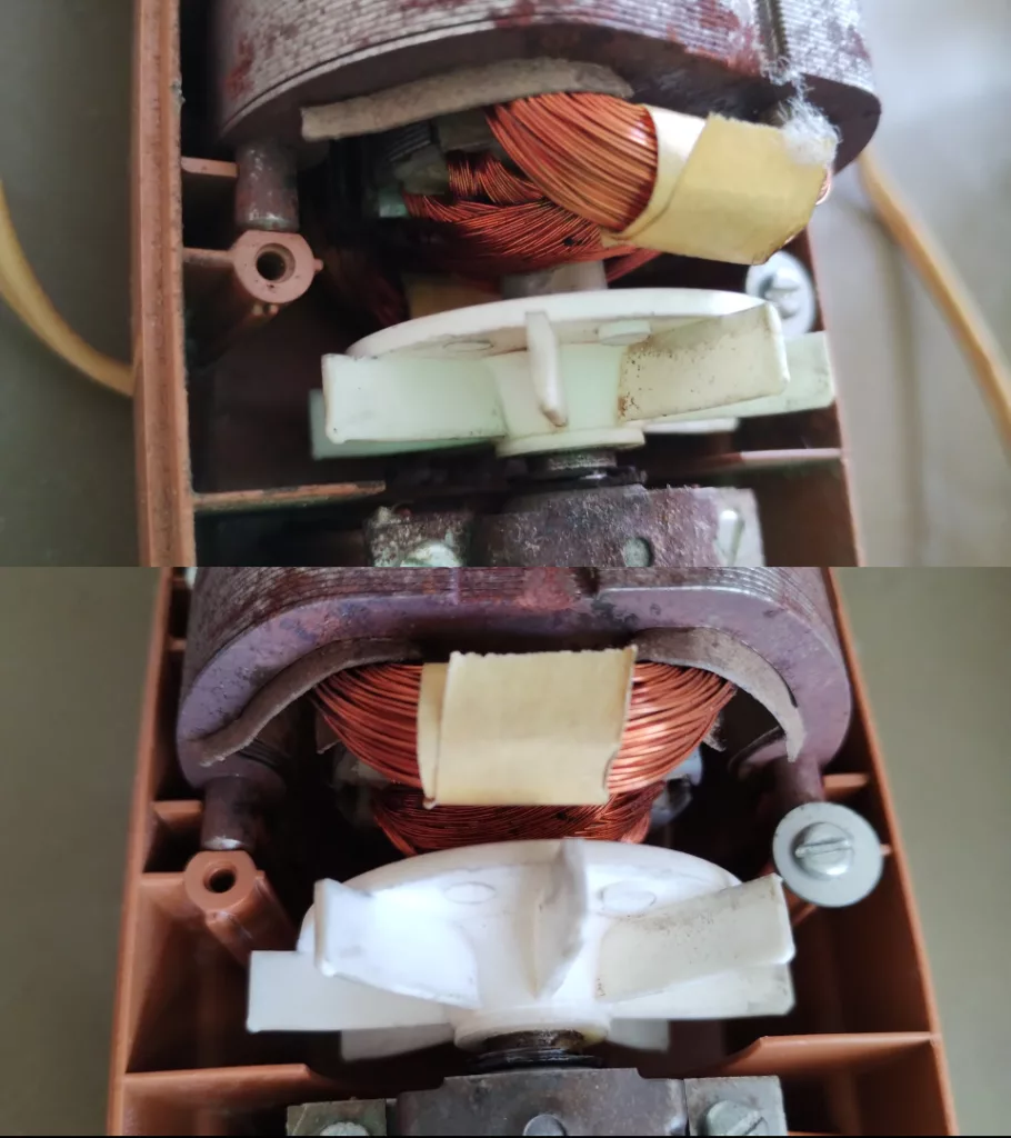
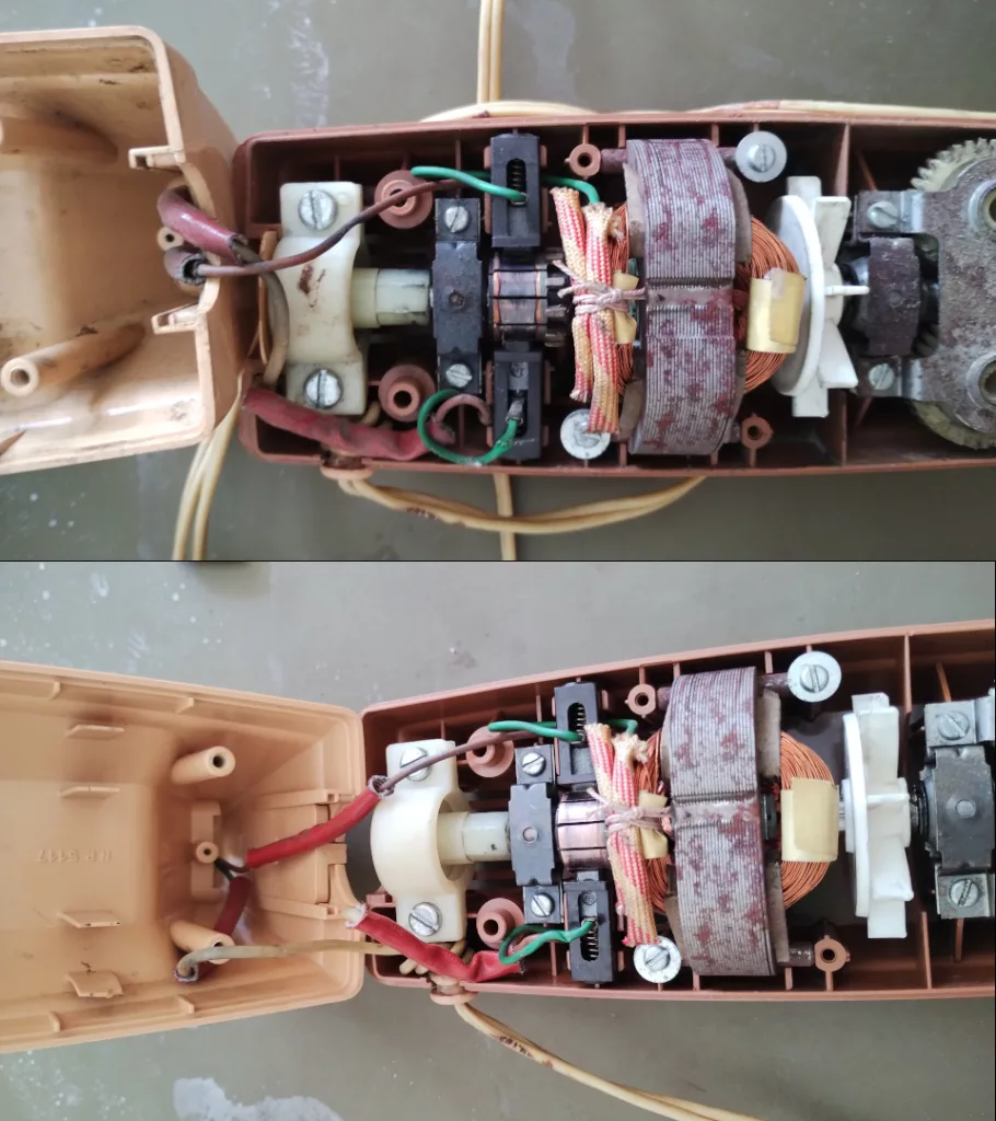
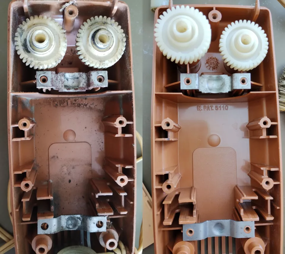
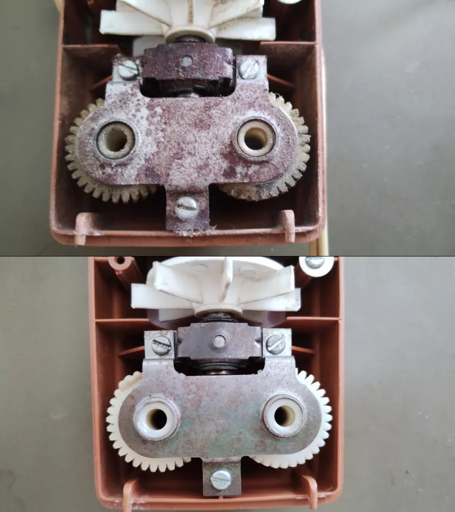
Motor and gears
The motor windings were dusted and cleaned with a soft plastic brush. The plastic gears were degreased with water and dish detergent, inspected, and re-lubricated with plastic grease.
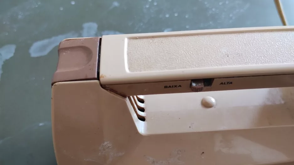
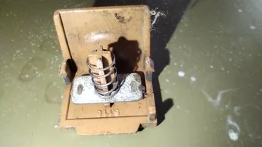
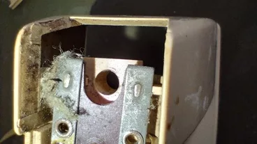
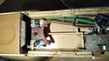
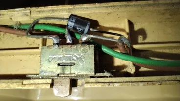
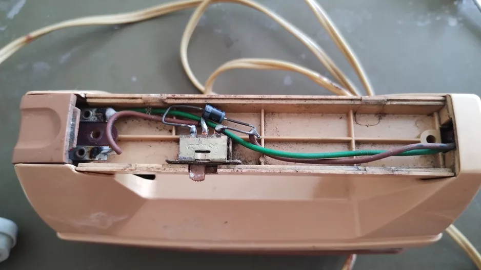
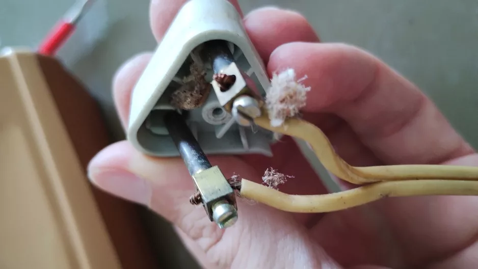
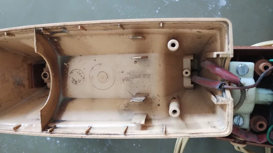
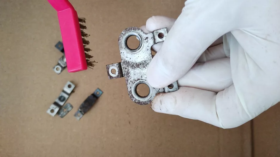
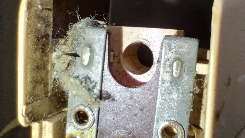
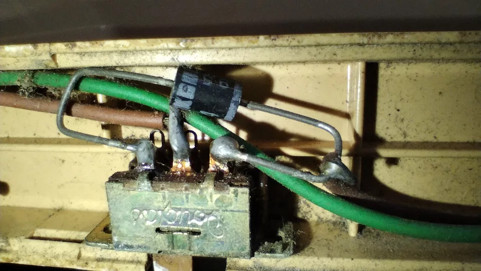
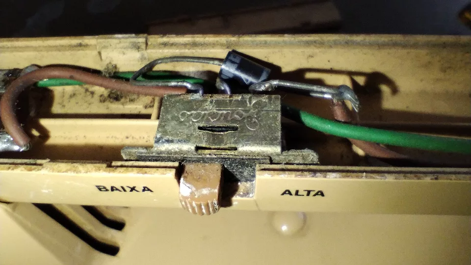
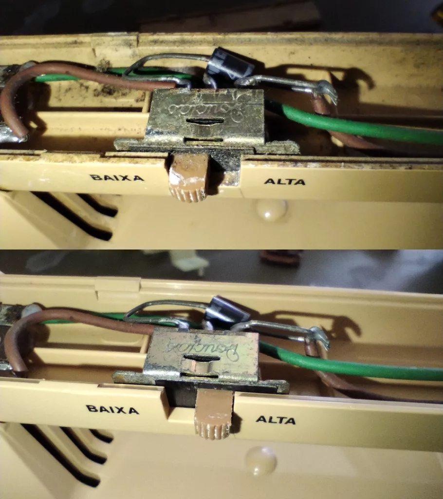
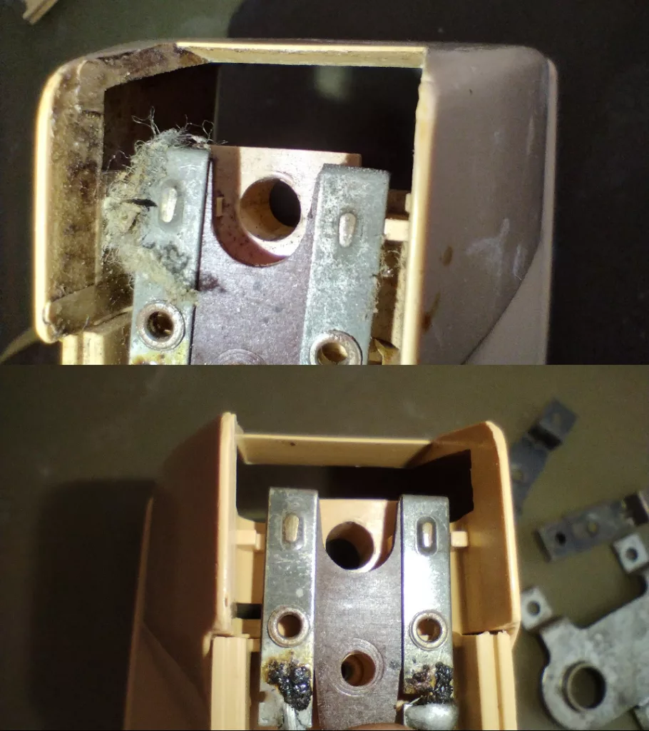
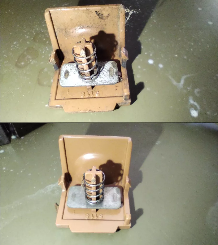
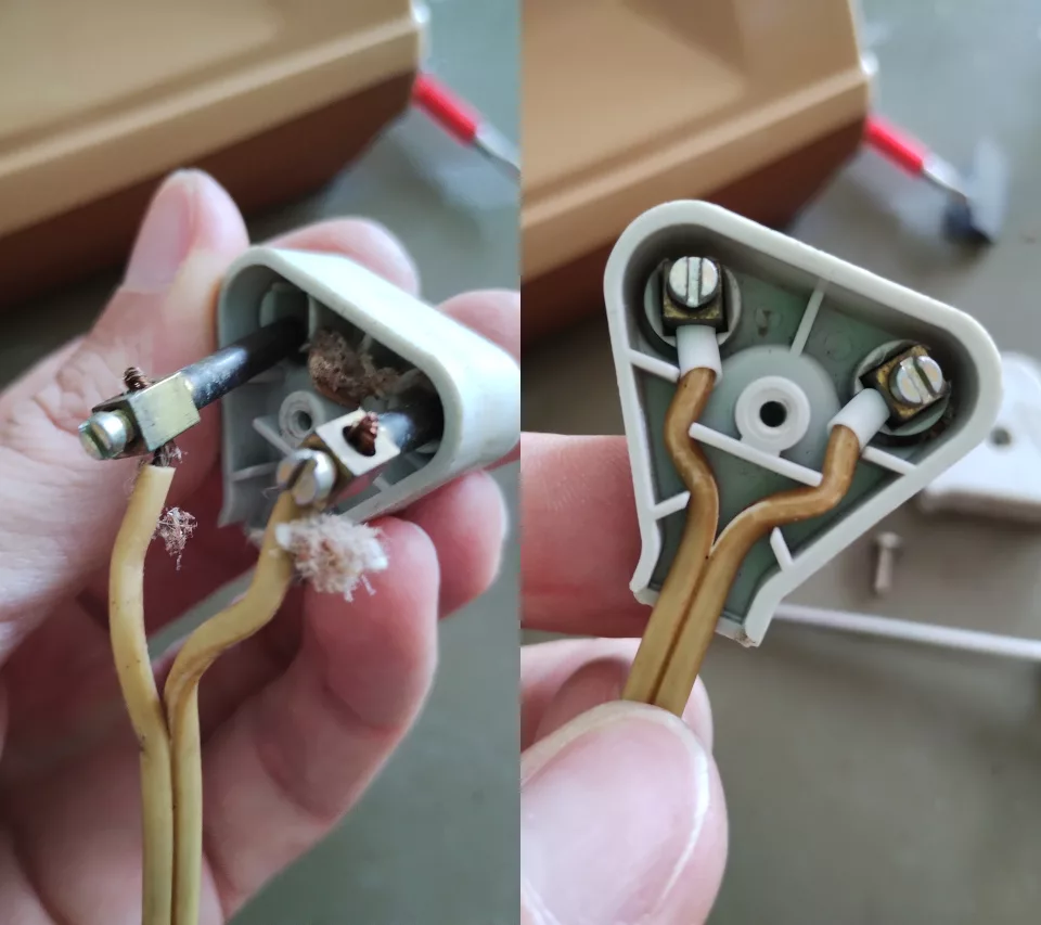
Electrical parts and wiring
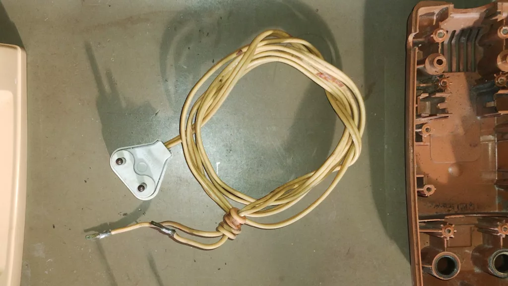
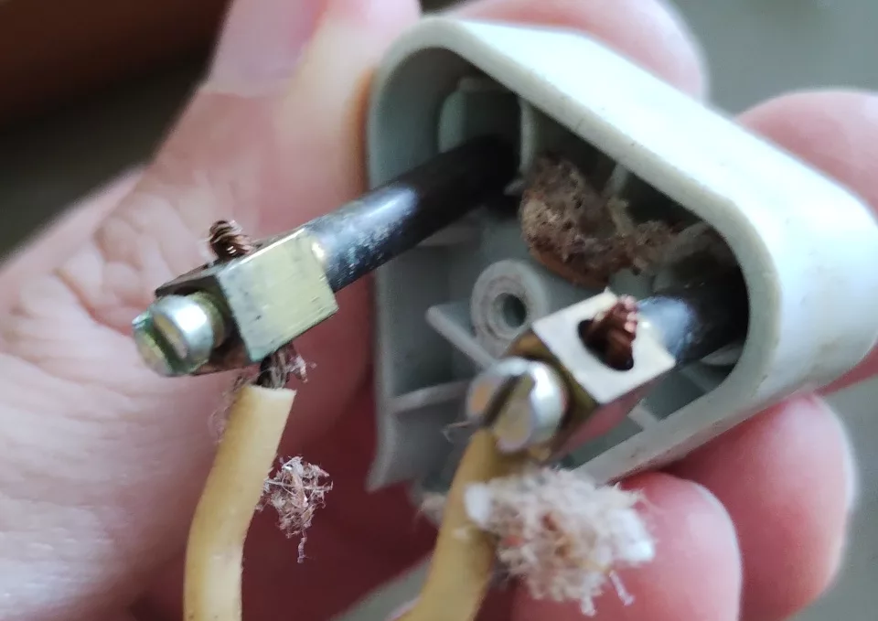
The internal contacts and switch were cleaned with querosene and a steel brush. The power cord was tested for any broken wires, cleaned with water and dish detergent, and the wall plug was inspected.

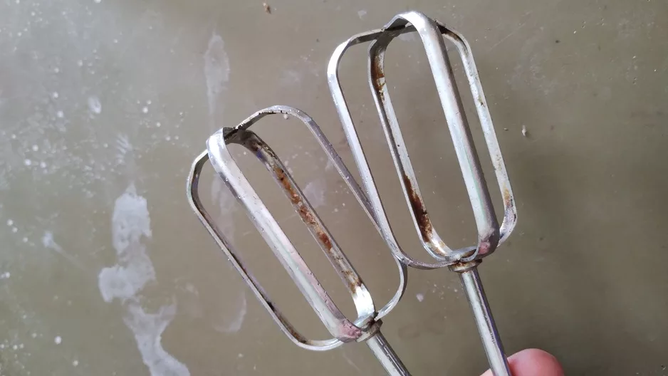
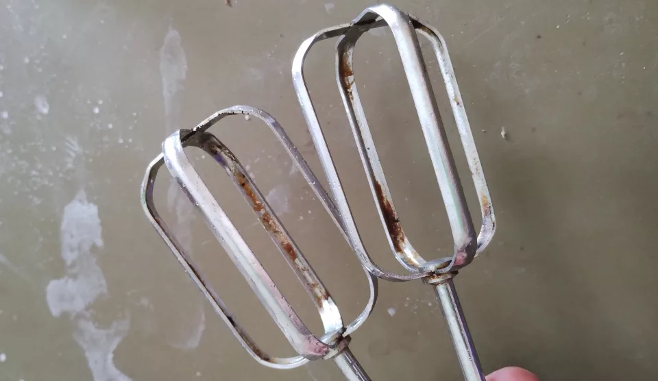
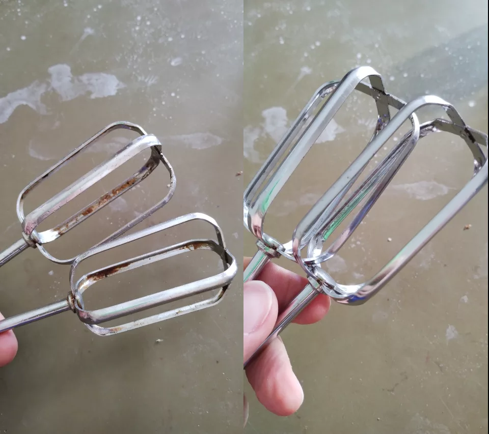
Beaters
A vinegar soak followed by gentle polishing with steel wool brought back the shine.
Final Result
The restored Arno MMA looks and works exactly like it did the day it left the factory. More importantly, it’s ready for another decade of service in the kitchen. Restoring old appliances like this is NOT about saving money, it’s about preserving a piece of history and memories and reducing e-waste.
See ya!