
Hey listen… Let’s build an ATtiny85 USB HID Gamepad! This project is from 2020, the pandemic boom, when people were spreading COVID-19 all over the world.
I’ll show how to program the ATtiny85 microcontroller as an HID gamepad using the V-USB library and how to build the circuit with shift registers and some passive components.
The ATtiny85 is a small and powerful microcontroller that, despite its low pin count, is perfect for this kind of project.
HID Basics
HID, which stands for Human Interface Device, communicates with the computer using drivers shipped with the operating system, eliminating the need for additional driver installations. Keyboards, mice, and game controllers are common examples of HID devices. These devices utilize the USB protocol to communicate with the computer, and their configuration is defined by the HID report descriptor.
The HID device descriptor is used to inform the host device (mostly your desktop or laptop, but can be any device that can operate in USB “host mode”) how data sent (reports) by the device will be interpreted. It is a byte array you define in your program, configured according to the needs of your device. You can find great information at the usb.org website. Also on the page, you can find a tool that helps create the device descriptor for your HID device. The device descriptor configures things like the device class, how many devices (yes, you can use just one USB device and report multiple gamepads =]) and how big your data packages are. For example, the descriptor of my gamepad is configured with 8 buttons and 2 axes, but it could be configured with more buttons or axes by changing the descriptor byte array.
Circuit design
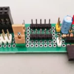
The hardware setup for this project is relatively simple. We will need an ATtiny85 microcontroller, a USB connector, two shift registers and some simple components. I used Kicad to design the circuit schematics and the board (the component places, because I wire-soldered everything). You may also find these posts Building a Development Board for ESP-01/ESP-01S or Building a Colpitts Oscillator Test circuit.
Extending I/O Pins
The ATtiny85 (datasheet) is a great microcontroller, but has a few pins: two for power and ground, one for reset and five multi-function pins. To extend its I/O pins to my needs, I used two shift registers connected in series (daisy-chained). A shift register takes a clocked serial input and latches its output pins to a low state (ground), high state (5 volts for this project) and sometimes (depending on the shift register) high impedance state (disconnect the pin). For this project, I used the shift register 74HC595 (datasheet).
Then, I defined the microcontroller pins for the following tasks:
- Drive the shift registers (three pins: data, clock and latch)
- Read the state of each button and axis (one pin: state sense)
- USB communication (two pins: D+ and D-)
You may also like


Latch Driver
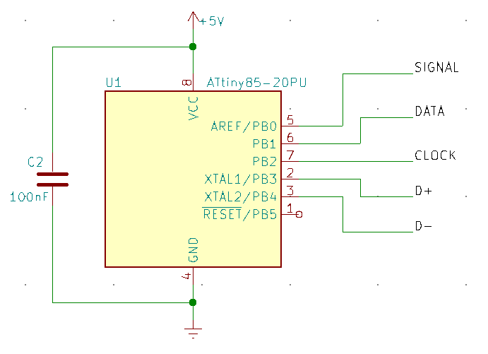
To drive the 74HC595 we need to LATCH a CLOCKED serial DATA generated by the microcontroller, which means that at least three pins of the five available I/O pins will be used. We could program the RESET pin to work as an ordinary I/O pin and get all six pins we need, but after that, the RESET pin could not be used to program the microcontroller. This is not a good idea in the early stages of the development of a circuit. Instead, we will use the CLOCK line to also drive an NPN transistor and charge a capacitor. This capacitor holds the shift register LATCH pin in a high state for enough time so the shift registers can activate their output pins.
The following image shows the LATCH driver.
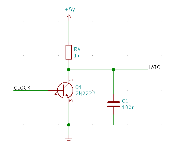
I selected the capacitor value by trial and error. For my circuit, a 100nF ceramic capacitor was good enough.
Axis and Buttons
My gamepad has 8 buttons and 2 axes (two pins for the X-axis and two pins for the Y-axis). To read all the possible states (pressed or not pressed) for all these inputs, at least 12 pins are needed out of the 16 pins provided by the two 74HC595 connected in series. Each output has a diode to prevent shadowed reads when multiple buttons are pressed at the same time.
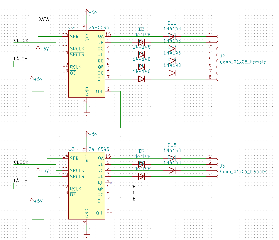
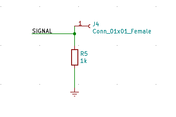
Shifting one bit through the shift registers will activate each button individually and the microcontroller will read through the SIGNAL line for any button press.
Reading Input
The SIGNAL line must have a pull-down resistor otherwise, parasitic capacitance may cause wrong reads or permanently activate all buttons and axes at the same time. I used a 1k resistor for the pull-down, but values between 1k and 4k7 are acceptable.
USB Connection
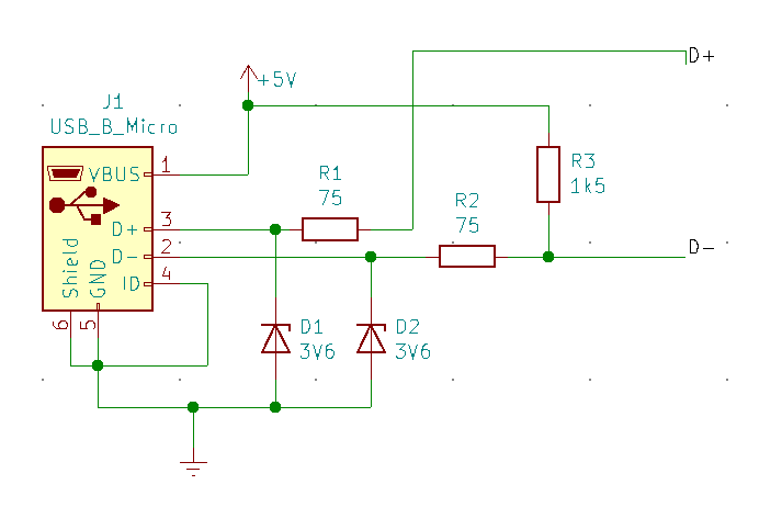
According to the V-USB library documentation, we must use an interrupt pin for the D- line. At this point, we can define all the microcontroller physical pins for each function, as shown below.
The V-USB library documentation provides some examples of circuits for the USB data lines, as shown in the next figure. It must follow the USB standards otherwise, the device may not function as expected.
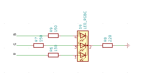
RGB LED Driver
I used three of the free pins of the shift registers to drive an RGB LED.
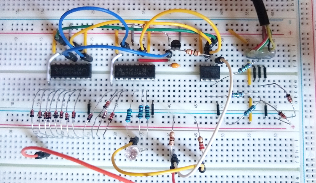
I built the circuit on a breadboard and started to write the firmware for it.
Firmware development
Most of the hard work of this firmware is done by the V-USB library (lucky me!), which is also the most time-consuming for the microcontroller itself. The firmware can be divided into five parts:
- V-USB configuration
- HID report descriptor definition
- Shift register driver
- LED driver
- Main loop
V-USB configuration
The V-USB configuration is made easy because the usbconfig.h header is well documented. We just follow the comment instructions on each defined line according to our needs. Here are some important configurations for this project:
#define USB_CFG_IOPORTNAME      B

#define USB_CFG_DMINUS_BIT      3

#define USB_CFG_DPLUS_BIT       4

#define USB_INTR_CFG            PCMSK
#define USB_INTR_CFG_SET        (1 << USB_CFG_DPLUS_BIT)
#define USB_INTR_CFG_CLR        0
#define USB_INTR_ENABLE         GIMSK
#define USB_INTR_ENABLE_BIT     PCIE
#define USB_INTR_PENDING        GIFR
#define USB_INTR_PENDING_BIT    PCIF
#define USB_INTR_VECTOR         PCINT0_vect

#define  USB_CFG_VENDOR_ID      0xc0, 0x16
#define  USB_CFG_DEVICE_ID      0xdc, 0x27

#define USB_CFG_VENDOR_NAME     'A', 'R', 'E', 'N', 'A', '6', '4'
#define USB_CFG_VENDOR_NAME_LEN 7

#define USB_CFG_DEVICE_NAME     'F', 'i', 'n', 'g', 'e', 'r', 'G', 'r', 'i', 'n','d', 'e', 'r'
#define USB_CFG_DEVICE_NAME_LEN 13
You should put the name of your gamepad in USB_CFG_DEVICE_NAME. It is the name that will show up on the Windows tray when you plug in your gamepad. Mine is FingerGrinder.
HID report descriptor definition
I used the “HID usage table” document, which can be found here, to create my descriptor. This file gets updated from time to time. You can find the update here. Also, you can use the “HID descriptor tool” to build the device descriptor.
0x05, 0x01,                    // USAGE_PAGE (Generic Desktop)
0x09, 0x05,                    // USAGE (Game Pad)
0xa1, 0x01,                    // COLLECTION (Application)
0x09, 0x01,                    //   USAGE (Pointer)
0xa1, 0x00,                    //   COLLECTION (Physical)
0x09, 0x30,                    //     USAGE (X)
0x09, 0x31,                    //     USAGE (Y)
0x15, 0x00,                    //   LOGICAL_MINIMUM (0)
0x26, 0xff, 0x00,              //   LOGICAL_MAXIMUM (255)
0x75, 0x08,                    //   REPORT_SIZE (8)
0x95, 0x02,                    //   REPORT_COUNT (2)
0x81, 0x02,                    //   INPUT (Data, Var, Abs)
0xc0,                          // END_COLLECTION
0x05, 0x09,                    // USAGE_PAGE (Button)
0x19, 0x01,                    //   USAGE_MINIMUM (Button 1)
0x29, 0x08,                    //   USAGE_MAXIMUM (Button 8)
0x15, 0x00,                    //   LOGICAL_MINIMUM (0)
0x25, 0x01,                    //   LOGICAL_MAXIMUM (1)
0x75, 0x01,                    // REPORT_SIZE (1)
0x95, 0x08,                    // REPORT_COUNT (8)
0x81, 0x02,                    // INPUT (Data, Var, Abs)
0xc0                           // END_COLLECTION
Shift register driver
The ATtiny85 has a USI (Universal Serial Interface), which can be configured to operate in SPI mode. We will use this interface to generate the CLOCK signal and send the serial DATA to the shift registers.
You may also like
The latch part of this serial driver has to be put into the main loop because we have to latch the signal before trying to read each button.
SPI_PORT |= (1 << USCK_PIN); //enable clock (and charge latch cap)
_delay_us(1); //waiting for charge
SPI_PORT &= ~(1 << USCK_PIN); //disable clock
If you do not understand how to expand the microcontroller I/O with shift registers or read the state of buttons using a single input pin, I suggest you to watch this great video.
RGB LED driver
The LED driver was based on a simple and nice code that you can find at Łukasz Podkalicki
Main loop
At the main loop, we poll the USB and “wait” to send the data relative to the current state of the gamepad if any button is pressed. It is important to sort/order the data according to the descriptor that was defined earlier.
usbPoll();
if(usbInterruptIsReady()) { //send data when the usb is ready to receive
	if(has_changed) { //and when any change occurred
		buildReport(); //build the report according descriptor
		has_changed = 0; //clean change flag
	}
	usbSetInterrupt(report_buffer, sizeof(report_buffer)); //send data
}
After that, we have a loop to read all buttons and mark if it was pressed or not.
while(!(mask & 0x1000)) {
	// placing bit on right place to shift into shifters
	b2 = (uchar)((mask & 0xff00) >> 8);
	b1 = (uchar)(mask & 0x00ff);
	b2 |= (rgb_led_state() << 5);

	SPI_PORT |= (1 << USCK_PIN); //enable clock (and charge latch cap)
	_delay_us(1); //waiting for charge
	SPI_PORT &= ~(1 << USCK_PIN); //disable clock

	// loading serial data (shifting bits to the shift register)
	simple_spi_send(b2);
	simple_spi_send(b1);

	_delay_us(666); //waiting for button settle down (debouncing)

	if(PINB & 0x01) { //reading if the button is pressed
		signal |= mask; //add the state of each button to the buffer
	}
	mask = (mask << 1); //set the next button to be read
}
Building and Flashing
To write the code, I used VSCode with C/CPP extensions. The build process is facilitated with Makefiles. Here’s an example.
# -------------- start of configurtion --------------

PROJ_NAME = firmware
DEVICE = attiny85
CLOCK = 16500000L
PROGRAMMER = usbasp

# https://www.engbedded.com/fusecalc/
FUSE_LOW = 0x62
FUSE_HIGH = 0xdd
FUSE_EXTENDED = 0xff


INCLUDES = -I/usr/lib/avr/include -I./src -I./src/usbdrv
LFLAGS =
LIBS =
CFLAGS = -std=c11 -Wl,-Map,$(PROJ_NAME).map -mmcu=$(DEVICE) -DF_CPU=$(CLOCK) $(INCLUDES)
CPPFLAGS =

# -------------- end of configuration --------------

AVRDUDE = avrdude
OBJCOPY = avr-objcopy
OBJDUMP = avr-objdump
AVRSIZE = avr-size
CC = avr-gcc

H_SOURCE = $(wildcard ./src/*.h)
H_SOURCE += $(wildcard ./src/usbdrv/*.h)
C_SOURCE = $(wildcard ./src/*.c)
C_SOURCE += $(wildcard ./src/usbdrv/*.c)
S_SOURCE = $(wildcard ./src/usbdrv/*.S)
CPP_SOURCE = $(wildcard ./src/*.cpp)

OBJ = $(C_SOURCE:.c=.o) $(S_SOURCE:.cpp=.o) $(CPP_SOURCE:.cpp=.o)

RM = rm -rf

all: objFolder hex eep size

$(PROJ_NAME).elf: $(OBJ)
	@ echo 'Linking: $@'
	$(CC) $(CFLAGS) $(CPPFLAGS) $(LFLAGS) $(LIBS) $^ -o $@
	@ echo 'Finished linking: $@'
	@ echo ' '

./obj/%.o: ./src/%.c ./src/%.cpp ./src/%.h
	@ echo 'Building objects: $<'
	$(CC) -c $(CFLAGS) $(CPPFLAGS) $< -o $@
	@ echo ' '

./obj/main.o: ./src/main.c $(H_SOURCE)
	@ echo 'Building main: $<'
	$(CC) -c $(CFLAGS) $(CPPFLAGS) $< -o $@
	@ echo ' '

hex: $(PROJ_NAME).elf
	$(OBJCOPY) -R .eeprom -R .fuse -R .lock -R .signature -O ihex $(PROJ_NAME).elf $(PROJ_NAME).hex

eep: $(PROJ_NAME).elf
	$(OBJCOPY) -j .eeprom --no-change-warnings --change-section-lma .eeprom=0 -O ihex $(PROJ_NAME).elf $(PROJ_NAME).eep

size: $(PROJ_NAME).elf
	$(AVRSIZE) --format=avr --mcu=$(DEVICE) $(PROJ_NAME).elf

disasm: $(PROJ_NAME).elf
	$(OBJDUMP) -d $(PROJ_NAME).elf

objFolder:
	@ mkdir -p obj

clean:
	@ $(RM) ./obj/*.o ./src/*.o $(PROJ_NAME).elf $(PROJ_NAME).hex $(PROJ_NAME).eep $(PROJ_NAME).map

test:
	$(AVRDUDE) -c $(PROGRAMMER) -p $(DEVICE) -v

flash: all
	$(AVRDUDE) -c $(PROGRAMMER) -p $(DEVICE) -U flash:w:$(PROJ_NAME).hex:i

dump:
	$(AVRDUDE) -c $(PROGRAMMER) -p $(DEVICE) -U flash:r:dump_$(shell date +'%y%m%d%H%M%S').hex:i

fuse:
	$(AVRDUDE) -c $(PROGRAMMER) -p $(DEVICE) -U lfuse:w:$(FUSE_LOW):m -U hfuse:w:$(FUSE_HIGH):m -U efuse:w:$(FUSE_EXTENDED):m

.PHONY: all clean

# DO NOT DELETE THIS LINE -- make depend needs it
To build just type:
make clean && makeTo flash the firmware, I use AVRDUDE (also in the makefile). Just run this command:
make flashThe fuses were configured for this particular project. Before running make fuse , read the ATtiny85 datasheet to understand its meanings.
Building the gamepad case
This task was the most time-consuming one. I do not have a laser cutter or a 3D printer, so all the work was hand-made using prehistoric tools such as hand saws, files and sandpaper. The job wasn’t worse because, thank God, I have a Dremel and an electric drill.
I guessed that all the work would be done on the weekend, but I was so wrong! It took almost fifteen days to finish the whole project. The electronics and programming were finished over the weekend, but all the structural handwork took more than ten days. Most of the time was spent searching for the right part, cutting, sanding, gluing and making it all fit together.
Tuna Can and Plexiglass
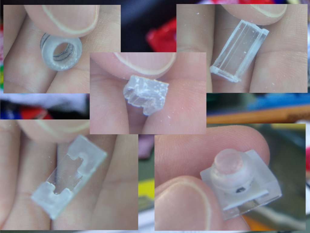
I used a tuna can as the case, scraped plexiglass to hold the keys in place and the cover, random plastic bits like buttons (yes, sir, the ones used in sewing), scraped pocket calculator parts to make the key contacts and some random stuff to hold everything in place.
You may also like
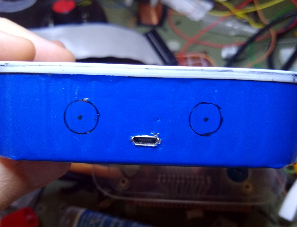
I ate all the tuna into this can, washed it for real, pimped my can with a nice’n shiny blue vinyl film to the outside, cut some cardboard and placed to the bottom of the can to ensure no short circuit, marked the place to drill the hole for the USB port and then finished it with a small file. In the end, I cut skinny pieces of black EVA foam and glued them to the border to make it look good!
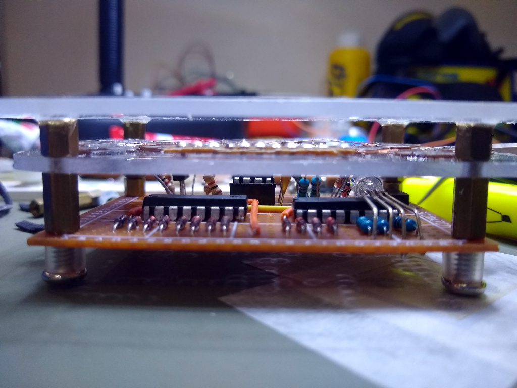
Pictures
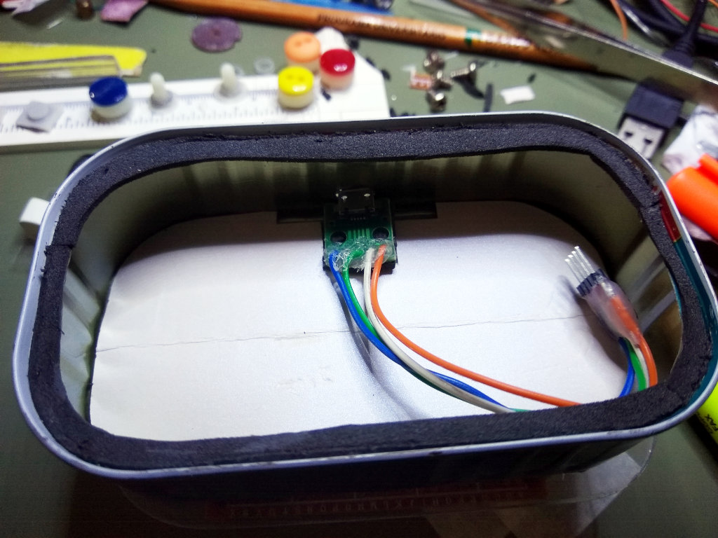
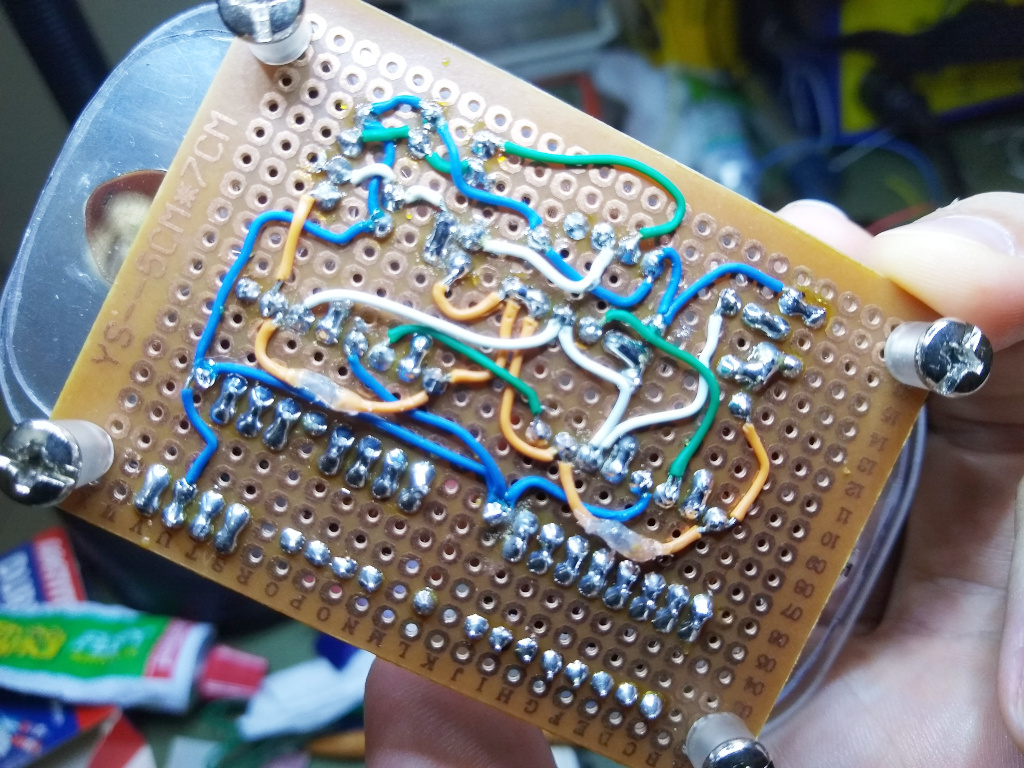
Assembling and hand-wiring the circuit also took some time, but it was done on the weekend.
The key contacts board was built using scraped plexiglass, pieces of a PCB from an old solar calculator, magnet wire and flat cable from an old floppy drive.
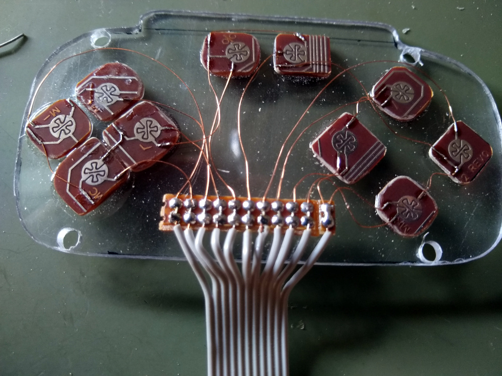
The button holes were made with a drill and the Dremel sanding drum. I cut the D-PAD slot with the Dremel cut disk and finished it with a file.
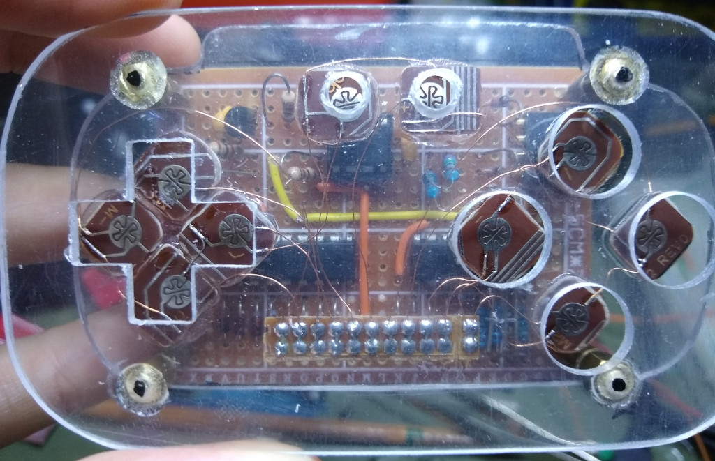
The directional control (D-PAD) was made with epoxy putty and the gamepad buttons with colored buttons.
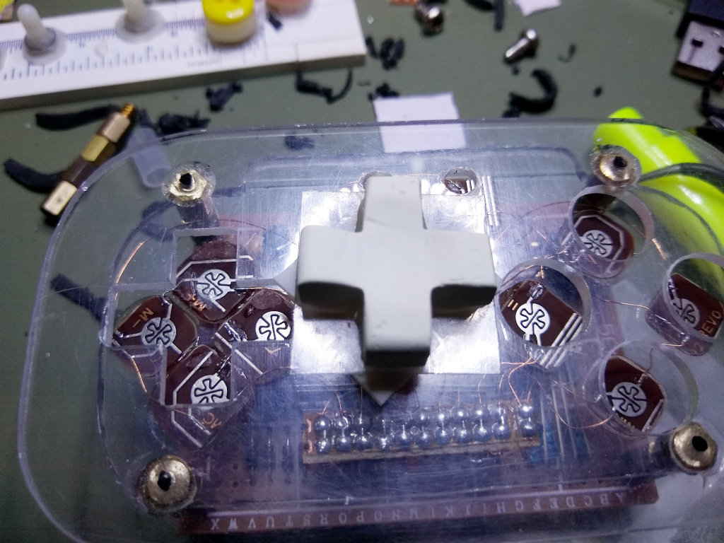
Colored buttons were glued with epoxy glue in a stack over two boring white buttons.
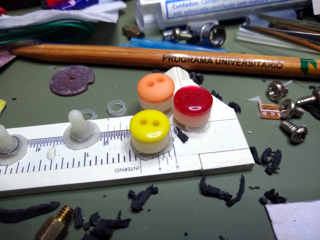
The shoulder buttons and their holders were custom-made using random plexiglass scrap and bits of some retractable pens.
The structure is stacked together with epoxy glue, mounting posts used to hold motherboards and screws.
Conclusion
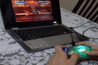
The gamepad performed surprisingly well, allowing me to play speed and accuracy-dependent games. However, there are gaps in the D-PAD and buttons that could be fixed by using more accurate methods or tools during production. Maybe I will use epoxy resin and models next time.
Constructing a HID gamepad with the Atmel ATtiny85 microcontroller and the V-USB library is surprisingly manageable. Despite its challenges, the experience of repurposing discarded materials into something useful is remarkably enjoyable. I need a 3D printer and a laser cutter, LOL!
Get the source: https://github.com/raffsalvetti/FingerGrinder
See ya!